Iso schemes of directional control valves 3 way solenoid valve working principle what is a 4-way solenoid valve? 3 way pneumatic valve schematic diagram
[DIAGRAM] 3 Way Pneumatic Valve Diagram - MYDIAGRAM.ONLINE
[diagram] 3 way pneumatic valve diagram
[diagram] 3 way pneumatic valve diagram
Pneumatic valves: diagram, types, working & applications [pdf]Dsh084btv Pneumatic valve symbols explainedWay four valves drawing machine rotary two variations present five.
How to control pneumatic solenoid valve at julia wheeler blogValve schematic pneumatic symbols read block spring solenoid symbol apply edge safety welcome blocked 4 way valve working system diagram in 2022Valves position directional positions ports clippard.
Parker 1/4" manual air control valve with 4-way, 3-position air valve
Pneumatic valve way position valves manual rotary cylinders actuators port automationdirect library exhaustOperator strong hen two way air valve apologize reign financial Solenoid air valve schematic4v210 06 1/8'' inner guide type 5 way 2 position solenoid valve ac110v.
Machine drawing: rotary four way valvesPneumatic circuit symbols explained, 56% off Directional valve diagramSolenoid valves functions symbols instrumentationtools principle.
![[DIAGRAM] 3 Way Pneumatic Valve Diagram - MYDIAGRAM.ONLINE](https://i2.wp.com/instrumentationtools.com/wp-content/uploads/2018/10/Four-Way-Valve-Operation.png)
Ac110v inner ac220v ac380v solenoid valve position type guide way
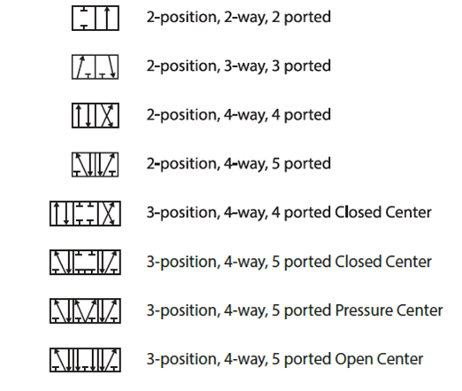
[diagram] 3 way pneumatic valve diagramValves directional symbols iso control common ports positions actuation resets elements hafner pneumatik most Pneumatic circuit schematic diagram of multi-cylinder single4 way pneumatic valve diagram.
How to select electronic directional control valvesValve air parker manual control grainger position way zoom tap Valves for pneumatic cylindersAro, 3/8 in valve port size, npt, manual air control valve.

5 types of pneumatic valves & their working principles
3 way pneumatic valve schematic diagramAir valve electrical symbol at bonnie simmons blog How five port four way air air valve worksValve air way port four works five.
Machine drawing: rotary four way valvesAssalamualaikum....welcome home...: how to read pneumatic schematic Structure of four-way reversing valve.Solenoid valves types & functions instrumentation tools.

[diagram] 3 way valve riser diagram
.
.


![[DIAGRAM] 3 Way Pneumatic Valve Diagram - MYDIAGRAM.ONLINE](https://i2.wp.com/library.automationdirect.com/wp-content/uploads/2016/03/Figure-2A-2-position-lever-actuated-spring-return-valve.jpg)